How to make simple 3-pin and 4-pin PWM pc fan speed control with Arduino. You can change the fan speed from off to max speed. Circuit will allow RPM control on any 12V pc fans. Tested with Noctua 120mm, Noctua 140mm PWM, NZXT and Artic Cooling.
If you tried analogWrite() function with mosfet to generate PWM signal and the pc fans made weird sounds and beeps, than this code will solve the problem. PWM frequency is 25 kHz, much higher than default timer frequency and the PWM speed control will be completely silent.
Code is the same for both type of fans. 3-pin circuit needs additional N-channel mosfet or some switching transistor. Arduino Uno or Arduino Pro Mini can generate 2 different PWM signals on pins D9 and D10.
I used this circuit to control 2 groups of fans with different speeds, 4-pin fan connected to pin D9 and mosfet with 3-pin fans on pin D10. Cheapest Arduino Pro Mini ATmega168 (5V, 16Mhz) can handle it.
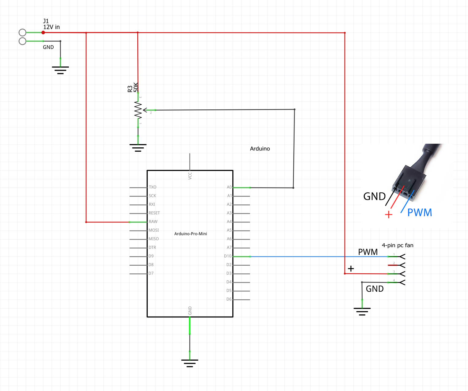
4-pin PWM pc fan control
Controlling the speed of 4-pin fan is very simple. Fan is connected directly to 12V and GND from power supply, no mosfet is needed for 4-pin fans. Arduino pin D10 is connected to PWM pin on 4-pin pc fan connector. Potentiometer can be replaced for thermistor or any other temperature sensor, as long as sensor output is converted to 0 – 320 range.
Example of map function converting 0 – 1023 sensor values to 0 – 320:
outputValue = map(sensorValue, 0, 1023, 0, 320);
analogWrite25k(10, outputValue);
To simplify the circuit even further, variable resistor can be omitted and PWM value 160 hardcoded in the code and the fan will run on 50% duty cycle.
Parts list:
- 50K potentiometer
- Arduino, e.g. Arduino Pro Mini ATmega168 (5V, 16Mhz)
Schematic:
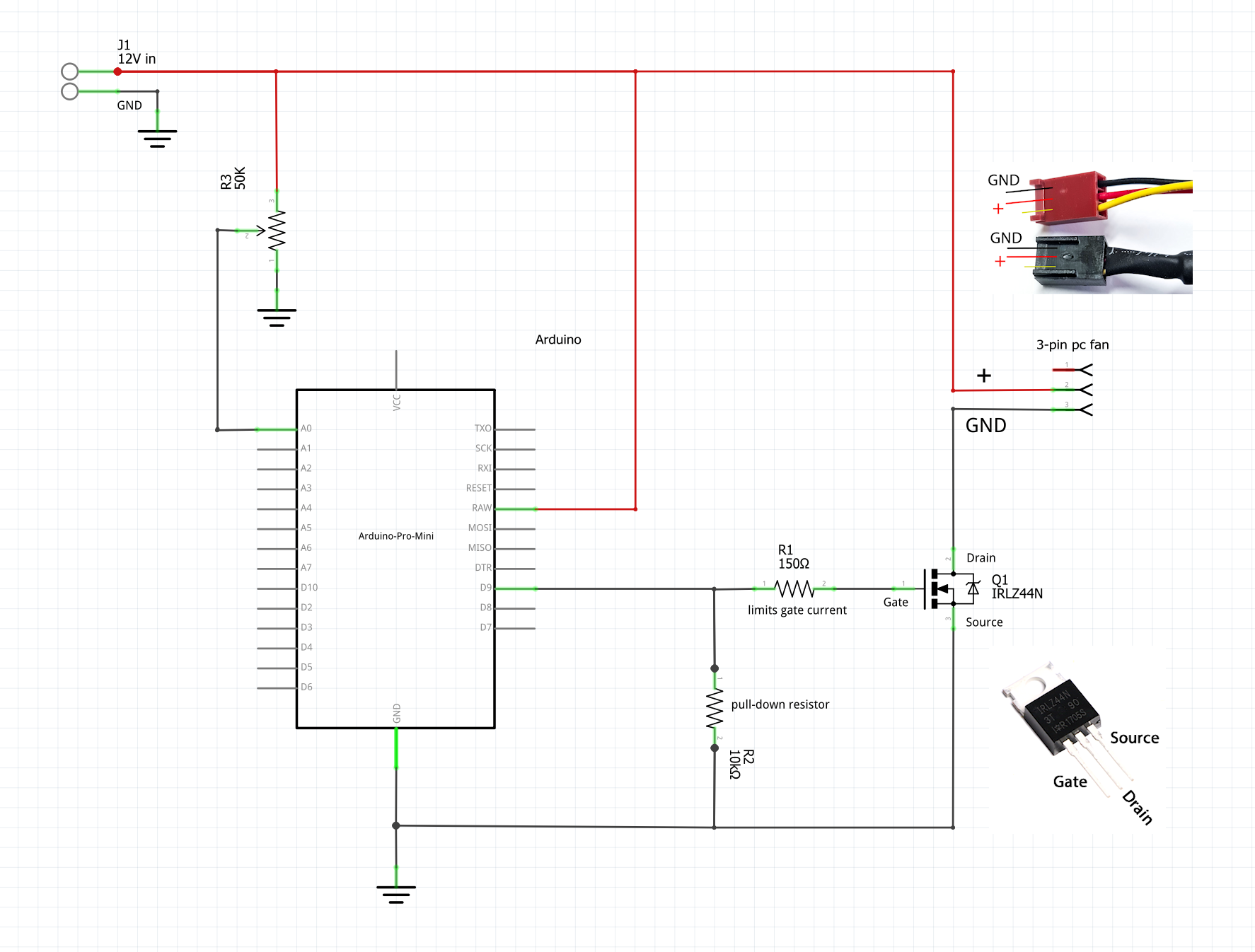
3-pin pc fan control
The same PWM signal used to control 4-pin fans can be used to drive the mosfet and control 3-pin fan instead. High PWM frequency will ensure quiet operation. 150 ohm resistor can be omitted but it’s there to protect the mosfet. 10K is not needed on most of arduino boards, but it will ensure best mosfet operation.
Parts list:
- N-channel mosfet, i used IRLZ44N
- 150 ohm resistor
- 10K resistor
- 50K potentiometer or trimpot
- Arduino, e.g. Arduino Pro Mini ATmega168 (5V, 16Mhz)
Schematic:
Code:
This code is for ATmega168 or ATmega328 @ 16 MHz. Arduino Uno and similar boards have only one 16-bit timer, that’s why only 2 outputs are available.
const int analogInPin = A0;  // Analog input pin that the potentiometer is attached to

int sensorValue = 0;        // value read from the pot
int outputValue = 0;        // value output to the PWM (analog out)

void setup() {
   // Configure Timer 1 for PWM @ 25 kHz.
    TCCR1A = 0;           // undo the configuration done by...
    TCCR1B = 0;           // ...the Arduino core library
    TCNT1  = 0;           // reset timer
    TCCR1A = _BV(COM1A1)  // non-inverted PWM on ch. A
           | _BV(COM1B1)  // same on ch; B
           | _BV(WGM11);  // mode 10: ph. correct PWM, TOP = ICR1
    TCCR1B = _BV(WGM13)   // ditto
           | _BV(CS10);   // prescaler = 1
    ICR1   = 320;         // TOP = 320

    // Set the PWM pins as output.
    pinMode( 9, OUTPUT);
    pinMode(10, OUTPUT);

}

// PWM output @ 25 kHz, only on pins 9 and 10.
// Output value should be between 0 and 320, inclusive.
void analogWrite25k(int pin, int value)
{
    switch (pin) {
        case 9:
            OCR1A = value;
            break;
        case 10:
            OCR1B = value;
            break;
        default:
            // no other pin will work
            break;
    }
}

void loop() {
    // read the analog in value:
    sensorValue = analogRead(analogInPin);

    // map it to the range of the analog out:
    outputValue = map(sensorValue, 0, 1023, 0, 320);

    analogWrite25k(10, outputValue);
}
Thanks to Edgar Bonet from stackexchange for 25kHz timer piece of code.