
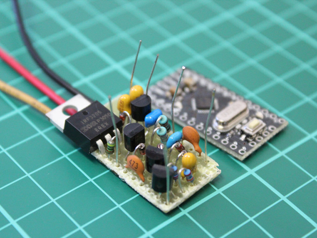
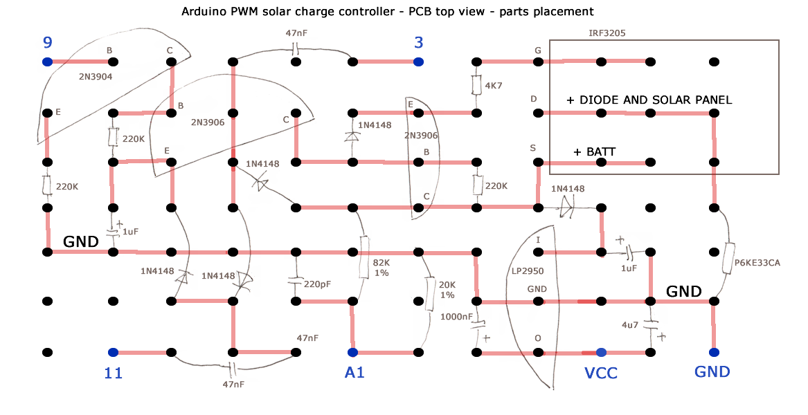
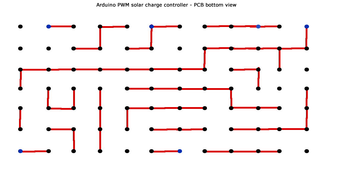
How to make very small, simple and cheap PWM solar charge controller with Arduino Pro Mini for 12V off-grid installations. The size of circuit board is the same as size of Pro Mini board, so they can be sandwiched together. PCB plans are for universal prototype board.
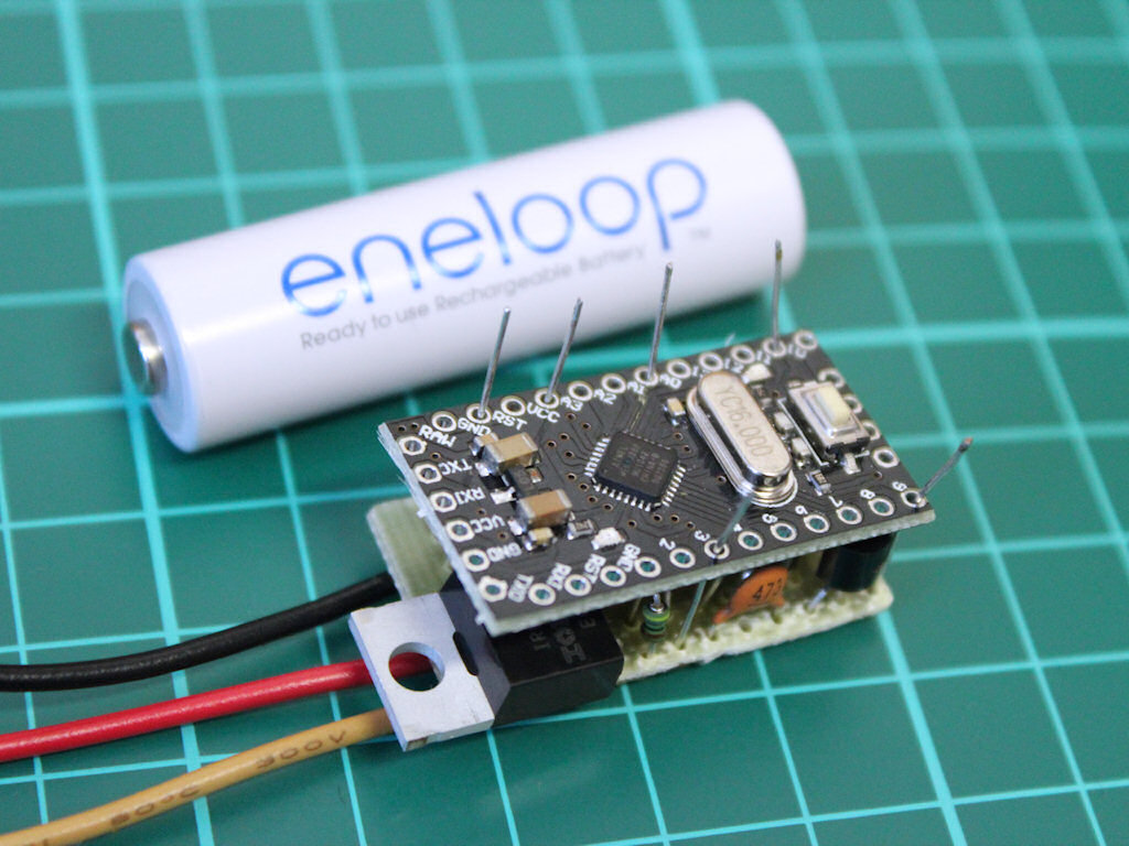
Connection and usage of this Arduino solar charge controller is very simple – there are 2 input leads from solar panel (+ and -) and 2 output leads going to the lead acid battery. Ground of solar panel and battery is joined together. Any load should be connected directly on battery terminals and charge controller will automatically handle the rest.
Arduino regularly measures lead acid battery voltage and according to detected value, switches the MOSFET on to charge battery from solar panel and switches MOSFET off when the battery is full. When your load pulls power from the battery, controller detects the voltage drop and immediately starts to charge battery again. During the night, when solar panel stops producing, controller waits until panel starts to output again.
Positive lead to the solar panel needs Schottky protection diode placed directly on the cable (wrapped in heat-shrink tubing). It’s not included in main PCB as this makes it easier to replace it and cool down at the same time. You could easily make the board a bit longer to fit in a different type of diode.
Schematic & function description:
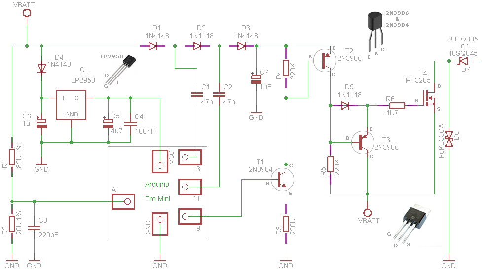
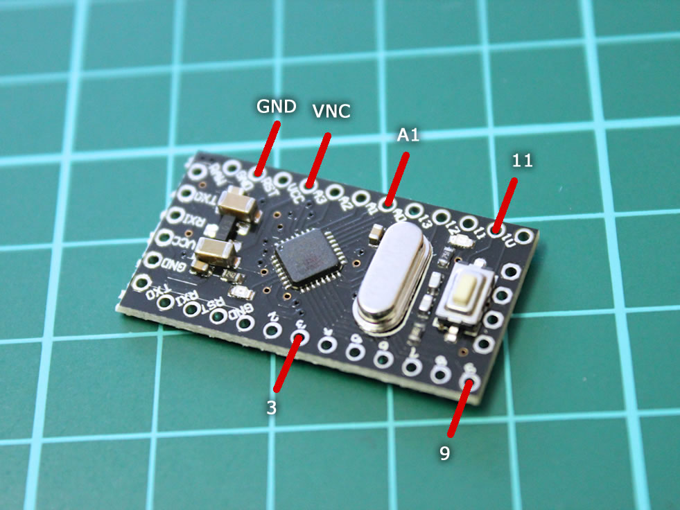
Function is based on N-Channel MOSFET IRF3205 in the high-side of circuit. This requires gate voltage higher than 12V to open the MOSFET properly. To omit the need for external MOSFET driver, it is driven by charge pump created with diodes, 2 capacitors and two Arduino PWM output pins (3 and 11). Pin A1 is measuring battery voltage and pin 9 controls MOSFET ON/OFF cycle. Arduino Pro Mini integrated LED connected to pin 13 is used to show off current PWM duty cycle.
Delete the code line
analogWrite(13, 255 - pulseWidth); // pwm to LEDif blinking LED bothers you too much.
Voltage Regulator and all the capacitors around (C6, C5 and C4) could possibly be excluded as there is a regulator included in the Arduino Pro Mini. However because I used cheap clone board, I am not willing to count on its ability to sustain higher voltages than 12V for longer time periods. LP2950 is very cheap and effective up to 30 Volts, so it’s worth to have it on board in any case.
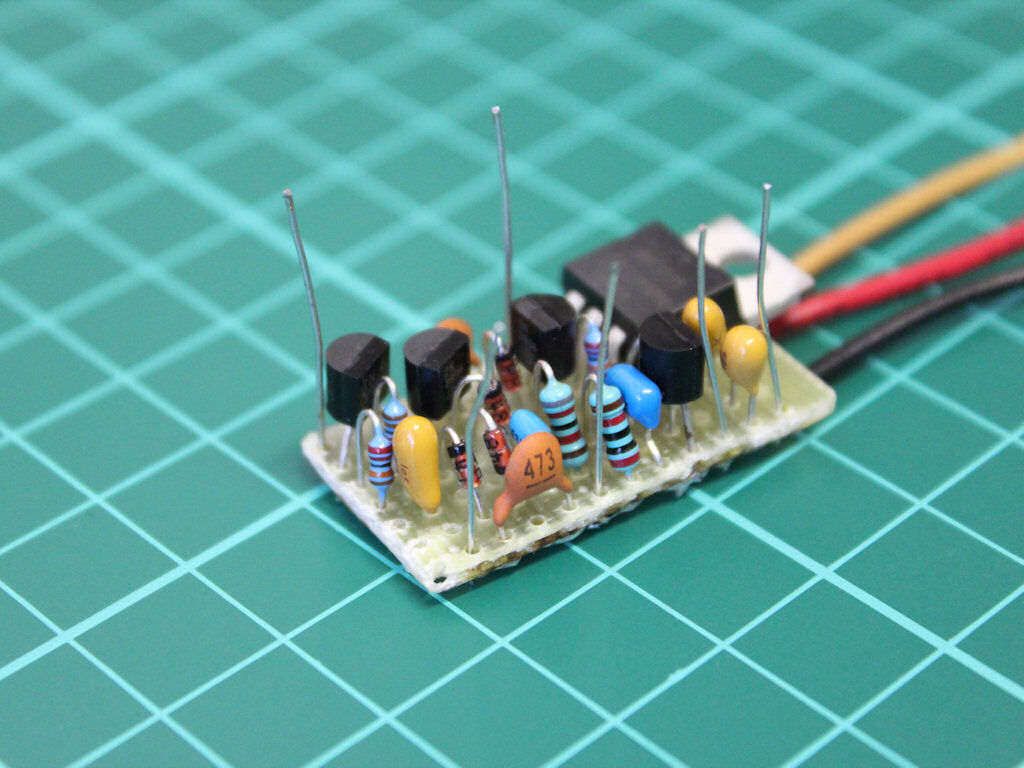
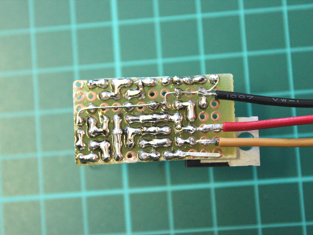
PCB – top & bottom view:
Parts List:
- Arduino
- Pro Mini ATmega328P 5V 16Mhz
- Low-Power Voltage Regulator
- LP2950ACZ-5.0
- Transistors
- 2N3904
- 2N3906 x 2
- N-channel mosfet
- IRF3205
- Resistors
- 82K (1%)
- 20K (1%)
- 220K x3 (0,4W is enough)
- 4K7 (0,4W is enough)
- Diodes
- 1N4148 x 5
- P6KE33CA
- 90SQ035 or any similar Schottky diode 35V minimum 9A (10A 45V or 20A 45V)
- Capacitors
- 47N/50V x2 ceramic
- 220P/100V ceramic
- 100nF/50V ceramic
- 4M7/10V tantalum
- 1M/35V tantalum x 2
Arduino code – basic version 1:
void setup() {
  TCCR2A = TCCR2A | 0x30;
  TCCR2B = TCCR2B & 0xF8 | 0x01;
  analogWrite(11, 117);
  analogWrite(3, 137);
//  Serial.begin(9600);
}

const int setPoint = 13.5 * 20 / (20+82) * 1024 / 5;
int measurement = 0;
int pulseWidth = 0;
int difference = 0;
int stepSize = 0;

void loop() {
  measurement = analogRead(A1);
  difference = abs(setPoint - measurement);
  stepSize = difference;
  if (measurement < setPoint)
  {
    pulseWidth += stepSize;
    if (pulseWidth > 255) pulseWidth = 255;
  }
  if (measurement > setPoint)
  {
    pulseWidth -= stepSize;
    if (pulseWidth < 0) pulseWidth = 0;
  }
//  Serial.println(pulseWidth);
  analogWrite(9, pulseWidth);
  analogWrite(13, 255 - pulseWidth); // pwm to LED
  delay(10);
}
Version 1.1 code with better blinking of pin 13 integrated LED according to PWM pulses:
const int setPoint = 13.5 * 20 / (20+82) * 1024 / 5;
int measurement = 0;
int pulseWidth = 0;
int difference = 0;
int stepSize = 0;
int calculation = 0;
int led = 13;

void setup() {
  TCCR2A = TCCR2A | 0x30;
  TCCR2B = TCCR2B & 0xF8 | 0x01;
  analogWrite(11, 117);
  analogWrite(3, 137);
//  Serial.begin(9600);
  pinMode(led, OUTPUT);
}


void loop() {
  measurement = analogRead(A1);
  calculation = setPoint - measurement;
  difference = abs(calculation);
  stepSize = difference;

  if (measurement < setPoint)
  {
    pulseWidth += stepSize;
    if (pulseWidth > 255) pulseWidth = 255;
    analogWrite(led, 0); // pwm to LED
  }
  if (measurement > setPoint)
  {
    pulseWidth -= stepSize;
    if (pulseWidth < 0) pulseWidth = 0;
    analogWrite(led, 255); // pwm to LED
  }
//  Serial.println(pulseWidth);
  analogWrite(9, pulseWidth);
  delay(10);
}
Arduino code download: arduino-pwm-solar-charge-controller.ino
Version 1.1 code download: arduino-pwm-solar-charge-controller-v1.1.ino
Schematic and code of this charge controller is by Julian Ilett, he is the mastermind behind this clever thing. All this is just a refined documentation and a suitable PCB design to perfectly fit Arduino Pro Mini board. He is sharing videos of more effective Arduino MPPT charge controller, but its construction is much more complicated and the project is not finished yet.
If you improve the code or construction in any way, please share your improvement in the comments smile
Hi.
How mich power may the solarpanel provide for this circuit? Is it suitable for a 100watts 12-18 volts panel?
Hi, 100watts panel is OK, maximum for shottky diode 90SQ035 is 150W, there will still be operational reserve. Just make sure cables soldered to mosfet leads are copper and thick enough (at least 1mm automotive cable).
Great! Thank you very much.
I have a substantial bank of batteries in an RV and am going to install solar panels. I have an Onan Gen to otherwise charge the batteries but it is manual turn on an turn off. Can a controller such as yours be added to the Gen to start it when the batteries fall below acceptable levels at (i.e. at night) and then turn it off when they reach the required voltage level – maybe through the use of a relay.?
Thank you
Steve Lukinuk
can you design same controller with 12v 2A and which show the charging current, Voltage power, remaining charging all about this on LCD also wifi data transmit….. Reply please…..
C4 is 100nF not 1000nF. Watch here: https://www.youtube.com/watch?v=MdgYXxQW0hA
1uF / 1000nF is recommended value in datasheet as output capacitor for LM2950-5.0. I used this value and circuit works OK :)
Hello,
Can this charge controller to use for the solar panel 240 w/p , maximun voltage 31v and 7,8 Amp.
Of not what must be the component to change to use this solar panel.
Thanks
Danbo
hi,
what modification is possible for 300w solar panel, battery 12v,
change only 90SQ035 or more components
big thanks,
tornier
Hi, correct you need to change 90SQ035 for a stronger Schottky rectifier (35A or more – 60CIQ045, 80CPQ150 or whatever you have available) mounted on a heatsink. Mosfet is rated for 110A, can handle 300W solar panel easily but needs aluminum heatsink too.
Here is a list of Schottky rectifiers from IRF, sortable by Amps:
http://www.irf.com/product/HiRel-Products-HiRel-Schottkys-Rectifiers-HiRel-Schottkys/_/N~1nje2p
Hello.
Many thanks for the work you’ve done in laying out the components in such a clever way. I’ve put it together and it works brilliantly. I’ve popped a video up on youtube with thanks to you and Julian Ilett for your hard work!
https://youtu.be/db1JZUecYlI
can we change the mosfet with a logic level mosfet ?the circuit will became a lot easier .. I believe we can :-) and also for the voltage regulator we can use an lm317 .. it’s also easier to find . For current mesurement and data export we can make a new version
hy frnds an i use this circut for a 150 watt panel where short crcut current is 9.08 ampere , is it charge the battery safly and prevent the overchargng and reverse chargng or not
is P6KE33CA Diodes is necessary ??
It’s there to protect mosfet and voltage regulator in case of voltage spike from solar panel. Not really necessary, but its cheap and it will ensure long life cycle of charge controller.
Can I use this code for arduino uno or arduino nano or arduino Leonardo pro micro?
hi Julian quick question would you be able to explain where each of these values came from just cant figure out where they came from:
const int setPoint = 13.5 * 20 / (20+82) * 1024 / 5;
thank you ryan
Apologie figured it out thanks great code
hi arduined
mbr2045
can i use the as replacement for the 90SQ035. ?
Hi, MBR2045 is OK.
Do you know if there is any variants of what you have created that can be used with wind turbines instead of solar. I am looking for a 24V system that should be able to handle up to 700Watts
can we use Arduino Uno instead??
Yes, Arduino Uno works as a replacement for Pro Mini.
Hi, I’m going to do this this weekend. Can I use a DC adapter as a power source instead of solar panel ?
12V DC adapter (the old heavy one with transformer inside) is great to simulate solar panel.
How would this cope with more than one controller on the chip.
Could the outputs from different mosfets be chained together
Yes they can be chained, it should work as long as each mosfet has its own R6 4k7 resistor. Mosfet chaining is often used in 12V to 220V converters, like this one http://www.eleccircuit.com/wp-content/uploads/2015/03/The-schematic-diagram-of-this-projects.jpg
Thankyou
Can it be connected to 100 watts solar panel and 60amp battery for running a load of 60watt/hr.
And if yes how much time it would support that load.
void setup() {
TCCR2A = TCCR2A | 0x30;
TCCR2B = TCCR2B & 0xF8 | 0x01;
analogWrite(11, 117);
analogWrite(3, 137);
// Serial.begin(9600); }
May I know whats the purpose of this code? thaanks
Code starts the internal oscillator on output pins 3 and 11. This is used for charge pump circuit consisting of D1, D2, D3 and C1, C2. When input (VBATT) is 12V, the output from charge pump (measured on D3) is around 20V.
Charge pump multiplies the voltage so mosfet works more effectively, with no overheating without the heatsink. It also allows N-Channel mosfet to switch positive side of the circuit, because voltage on mosfet Gate is much higher (20V) than voltage on mosfet Source-Drain (12V).
thanks for that! may I know the full ratings of your charge controller? and can i still use this when the voltage max output from solar panel is 24V? thanks
Is this circuit can be used for charging a 24V battery? Help me modifying this circuit
24V panel will max around 37 – 38V. Mosfet should handle 55V but LP2950 only up to 30V. 7805 alternative is even worse so you will need to use some voltage divider before LP2950 or scrap the 5V linear stabiliser circuit completely (including C6, LP2950, C5 and C4) and use LM2596 step-down DC-DC converter module to power the arduino instead.
2N3906 should also be replaced for some higher voltage generic PNP transistor, 2N3904 for generic higher voltage NPN transistor. All capacitors will need to have higher voltage rating, C7 should be rated for 60-70V. P6KE33CA needs to be removed or replaced with P6KE50CA.
const int setPoint = 13.5 * 20 / (20+82) * 1024 / 5;
can you tell me what is 13.5 , 20 , 20+82 ?
thank you
Its voltage divider formula, two resistors R1 and R2 take a higher voltage (more than 12 Volts) and covert it to lower voltage (less than 5 Volts).
Voltage divider output is calculated by
Vout = Vsource x R2 / (R1 + R2)
Vsource is the target charging voltage for lead acid battery – 13,5 Volts
Vout is measuring voltage on Arduino analog pin A1
Vout = 13.5 Volts x 20 kOhm / (20 kOhm + 82 kOhm)
Vout = 270 / 102
Vout = 2.64 Volts
So voltage of 13.5 Volts will result in 2.64 Volts at analog pin A1. Maximum 5 Volts measuring voltage will be reached at battery voltage of 25.5 Volts.
hi arduined,
can i use an ultrafast recovery diode (MUR1560) as replacement for the 90SQ035 ? ( 90SQ035 is not available to me )
Yes you can but its not Schottky diode so it has higher voltage drop, it might get a bit hot and will most likely need a heatsink. Schottky diodes have very low forward voltage drop and they will be much more effective in this circuit. I now use this cheap alternative 5pcs 10A 45V Schottky Rectifiers from ebay https://www.ebay.com/itm/5pcs-10SQ045-10A-45V-Schottky-Rectifiers-NEW-/401113013863
For more powerful solar panels this one 20A 45V 20SQ045 https://www.ebay.com/itm/10pcs-20SQ045-20A-45V-Schottky-Rectifiers-Diode-Brand-New-R-6-/271903359245
Thanks a lot Arduined. Really appreciate your work .
battery 12v 100Ah
Pmax = 140 Watt,
Isc = 8.39 A,
VOC = 22 V
What is all the changes to hardware and software?
I have built this. There is one issue i am having. The calculation for setpoint comes out to a value of 542. however, my battery with the voltage divider at 13.5 volts being read in is showing a reading of 810.
So the code will ALWAYS show measurement > setPoint.
Any thoughts? it seems that if this case happens. The pwm = 0. This means it’s charging right? cause the LED is turned on (255 – pulseWidth) is that right? 0 = charging. 255 = no charging
any idea on my reference voltage?
Thats right. Setpoint 542 and my Serial.print(analogRead(A1)); is 537 at 13.53 volts. Your reading of 810 is plain analogRead(A1) value? Are you using precision 1% resistors for R1 82K and R2 20K? There are no other parts involved for measuring voltage, only those 2 resistors.
Try this to see battery voltage measured with arduino:
float batteryVoltage = 0;
batteryVoltage = (analogRead(A1) * 4.99 / 1024) * 5.161;
Serial.print(“analogRead: “);
Serial.println(analogRead(A1));
Serial.print(“batteryVoltage: “);
Serial.println(batteryVoltage);
Serial.print(” “);
they might be 2% resistors. I added that bit of code. It’s showing my battery voltage at 19.84v now lol
haha i think i figured it out. this pro mini is a 3.3v LOL as soon as I changed the setpoint voltage equation to
const int setPoint = 13.5 * 20 / (20+82) * 1024 / 3.3 ;
my code is showing the setpoint now as 13.5 = 871 and my analogread is showing 789 and reporting 12.71 for voltage. my multimeter is showing around 12.89. It’s not spot on it but it’s WAY closer than it was
Nice :)
You can calibrate it spot on with voltmeter
batteryVoltage = (analogRead(A1) * 4.99 / 1024) * 5.161;
4.99 is output voltage from arduino voltage regulator
yours is somewhere around 3,243
batteryVoltage = (analogRead(A1) * 3.243 / 1024) * 5.161;
which reads 12,89 V at analogRead 789
Thanks a ton! You definitely helped me get to the end goal. So version 1 of this board is built and going to be added to my bike generator project.
https://www.youtube.com/watch?v=ZnOdGsqDfI8&list=PLpGbjnsmeLnCb7Oqr6zBZKd7dTDH8fZhn
The next part will be discussing this controller as part of the build :)
also on mine the A pins are reversed. so where yours queries a1 i have to query a3.
Hi Julian,
could You pleae explain me, how exactly the charge pump works? Why you don´t set the first five bits, especially WGM bits in TCCR2B? I want to understand, how the timer worked :-(.
TCCR2A = TCCR2A | 0×30;
TCCR2B = TCCR2B & 0xF8 | 0×01;
analogWrite(11, 117);
analogWrite(3, 137);
Thank You very much!
Jack
TCCR2A 0x30 or TCCR2A 0b00110000 sets only bits COM2B1 and COM2B0 to 1 which inverts the pulse.
TCCR2B = TCCR2B & 0xF8 | 0×01 or TCCR2B = TCCR2B & 0b11111000 | 0×01 sets pins 11 and 3 PWM to 31kHz.
if you use other setting instead of 0x01 it will set different divisor and frequency
0x01 – 31372.55 Hz
0x02 – 3921.16 Hz
0x03 – 980.39 Hz
0x04 – 490.20 Hz
0x05 – 245.10 Hz
0x06 – 122.55 Hz
0x07 – 30.64 Hz
BTW, i am not Julian, i only studied his circuit :)
Maybe I figured it out. You only set inverted mode for OC2B – pin 3 in TCCR2A and no presampling in TCCR2B. No interrupts, timer is used. If I am right, my only question is, if the both analogWrite values will be the same, e.g. 127, will that make higher voltage on charge pump? It seemes to me, that You intentionally change the values, so some pulses should be overlapped and slightly decreasing the maximum voltage of charge pump. Is that right?
Please excuse my poor English…
Thank You.
Jack
Hi, Dickson charge pump with diodes should not have overlapping waveforms. Having something like a 10% reduction in pulse width so the signals don’t overlap improves efficiency of the charge pump.
Thank You very much for explaining and sorry for the name :-). I have last question. You wrote: “During the night, when solar panel stops producing, controller waits until panel starts to output again.”
But there is nothing in code what could do that, in my opininon, the controller will set pulsewidth 255 during the night, but there will be no power coming out of the panel. Is that right? I want to use it my car, for charging battery in winter with 18V/1A solar panel, but i will add some discharge pulses because of desulfatation. I have charger with 2051 which charge 9 pulses and 1 discharge pulse, when it reach 13.8V, it charge 1 pulse + 1 discharge puls. But it is powered by small transformer 24V/2W and it’s not suitable for solar panel.
Right, arduino loops until solar panel starts producing power again in the morning. Interesting idea about desulfatation, maybe you could use code modification i made some time ago. I added RGB led to visually indicate charging and state of batteries, its used on my solar setup and works great.
https://www.arduined.eu/files/arduino-pwm-solar-charge-controller-v2-rgb-led.ino
You could modify the voltage values for your needs and add some discharge circuit activation when battery is fully charged on line
} else if ((batteryVoltage > 13.40) && (batteryVoltage < 13.80)) {
setColor(0, 255, 0); // green
}
For RGB i used this cheap common anode LED with 1k or 4k7 resistors on pins 5,6,7 https://www.ebay.com/itm/10Pcs-LED-DIFFUSED-RGB-common-anode-4-PINS-F5-5MM-Super-Bright-Bulb-Lamp/221993821141
When charging RGB blinks green, when not charging and batteries are above 13.4 Volts it stays green. Between 13 to 13.4 its bright yellow, below 13 Volts dimmer yellow and when battery bank drops below 12.50 it gets red.
Hi,
sorry for late answer but I read it today. Thanks very much for the code, but I have already made prototype with few modes, LCD and I want to include high side current measurement with operational amplifier, and make the charger more universal – connect NB adapter or another power source instead of solar panel and charge battery at home with higher current.
I wish You the best for the new year!
Jack
Can i replace 220k with 260k.?
And voltage regulator Lp2950 with 7805.?
Thanks
And IRF3205 with IRF540
Bacuase my solar penal is 150watt
Help me plz.?
IRF540 has insufficient continuous drain current, only 20A. IRF3205 has 80A. IRF540 should work for 150W panel, but to be safe, put more of them in paralel and also mount them on heatsink. IRF3205 has very low RDS drain-to-source resistance, only 0.008 ohms and it remains cold even without heatsink. 540 has almost 10 times the resistance 0.077 ohms and it will definitely warm up.
260k for 220k should be ok. 7805 will work, but will drain your battery little bit faster during the night and 7805 will probably need some heatsink, it will run hotter than LP2950.
Can you give the link of the battery you used in this project.Also whats the logic behind the setting of setPoint { const int setPoint = 13.5 * 20 / (20+82) * 1024 / 5; }.
I will be very grateful if you reply.
I use car batteries. Logic behind setPoint const is setPoint = (desired battery voltage) * R2 / (R2+R1) * 1024 / 5
CAN WE USE IN5408 INSTEAD OF 90SQ035?
3A max current is too low and non-Schottky diode will heat up a lot. If your solar panel has a diode integrated you dont need it at all.
How many volts does the charge pump provide to the MOSFET?
Charge pump provides around 20 Volts to the MOSFET gate.
It seems your schematic drawing was done in Eagle. Would you share the file, I would like to make the circuit board.
Many Thanks
Pedro
Yes Pedro, uploaded the Eagle schematic file here: https://www.arduined.eu/files/arduino-pwm-solar-charge-controller.sch.zip
hope it helps :)
perfect, very many thanks
what is the working voltage range of the charge controller?
Working input voltage range is 0 to 29V. At 33V protection from P6KE33CA kicks in to save other components.
Thank you for sharing this circuit. Will def be building this!
I see you apparently change the frequency, could you explain why and let us know how the lines of code work?
I found my answer right above, sorry.
Hi – I am looking to extend this controller by adding a few more components on a second ‘daughter board’ such as an OLED display, and a couple of INA219a voltage & current monitors, BMP280 temperature sensor etc. etc. The extra components would be on a separate board which can be added or removed as required, with a separate ESP8266 micro-controller to make the whole thing web-enabled, and to avoid interfering with the timings on the main AtMega328p PWM5 board. The PWM5 board essentially remains as a standalone Atmega328p PWM5 charge controller, and the second board can simply be added as a separate web-enabled monitoring station.
Ideally I would like the daughter board to be powered from the same 5v rail generated on the main PWM5 board, however the LP2950ACZ-5.0 voltage reg can only supply a max 100ma which would not be enough to power the daughter board – so I was thinking of swapping it for an AMS1117 5v reg instead which can provide max 800ma. (Obviously I would also change the output capacitor to 22uF as per AMS1117 datasheet.)
This way the second board can be powered from the same 5v rail from the AMS1117 on the PWM5 board, sharing a common GND. This is what is so great about Julian’s PWM5 design – common GND rather than common Positive that most cheap PWM charge controllers seem to have. The INA219a voltage/current sensors can then monitor the battery voltage and solar panel voltage & current.
Can you see any downside of this approach – specifically replacing the LP2950ACZ-5.0 vreg with an AMS1117-5.0 (other than the extra ~100ma current draw from the battery by the daughter-board) ?
Thanks,
Mike
Hi Mike, it should work great. Only downside would be need to heatsink AMS1117-5.0, it will run hotter compared to LP2950ACZ-5.0. Chip should handle 125°C but for long-term 24/7 operation, i would give it big copper pad on the PCB to make it run as cool as possible. This design is really great and stable, its running flawlessly every day for 5 years or more.
Hi (again) – can you please confirm the maximum voltage rating of the Solar panel(s) that can be connected to this circuit? By my reckoning, if the (car) battery is down to say 11v, the PWM signal on Pin9 will be 255, which will cause the various transistors to turn on, and in turn turn on the MOSFET. When the MOSFET is turned on, all the voltage from the solar panel will effectively connect directly (through the MOSFET) to VBATT – so if you have a really sunny day and the solar panel is generating (say) 23v you will have the full 23v going straight into the car battery.
Is my understanding correct?
Any 12V solar panel. Mine are 12V panels with Vmp of 18,80 V. Open circuit voltage around 20-21 V. This is verified working output and will never damage lead-acid battery as the circuit will open and close the mosfet many times per second to average out the output according to measured battery voltage through pin A1. So your understanding is correct for fraction of a second, then it will turn off, then on again.
Code below should be more readable than original code, if you connect simple 4pin RGB led to pins 5,6,7 and add the code, it will help you see what is going on. Led will not stay green (charging) constantly in full sun, it will blink as the mosfet is opening and closing:
(… are parts of original code)
….
float batteryVoltage = 0;
int redPin = 7; // RGB LED red pin
int greenPin = 6; // RGB LED green pin
int bluePin = 5; // RGB LED blue pin
void setup() {
…
pinMode(led, OUTPUT);
pinMode(redPin, OUTPUT);
pinMode(greenPin, OUTPUT);
pinMode(bluePin, OUTPUT);
}
void loop() {
…
batteryVoltage = (analogRead(A1) * 4.99 / 1024) * 5.161;
Serial.print(“batteryVoltage: “);
Serial.println(batteryVoltage);
Serial.print(” “);
if (batteryVoltage < 12.00) {
setColor(0, 0, 0); // turn off RGB
} else if ((batteryVoltage > 12.00) && (batteryVoltage < 12.50)) {
setColor(255, 0, 0); // red
} else if ((batteryVoltage > 12.50) && (batteryVoltage < 13.00)) {
setColor(155, 155, 0);// dim yellow
} else if ((batteryVoltage > 13.00) && (batteryVoltage < 13.40)) {
setColor(255, 255, 0);// yellow
} else if ((batteryVoltage > 13.40) && (batteryVoltage < 13.80)) {
setColor(0, 255, 0); // green
} else if (batteryVoltage > 14.40) {
setColor(255, 0, 255); // red – overcharging
}
…
}
void setColor(int red, int green, int blue)
{
red = 255 – red;
green = 255 – green;
blue = 255 – blue;
analogWrite(redPin, red);
analogWrite(greenPin, green);
analogWrite(bluePin, blue);
}
Perfect – thanks for the clarification (& I like the idea of using an RGB led to better indicate current charging status). Many thanks.